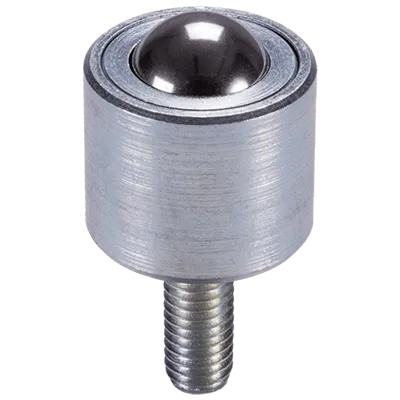
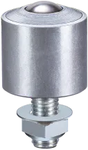
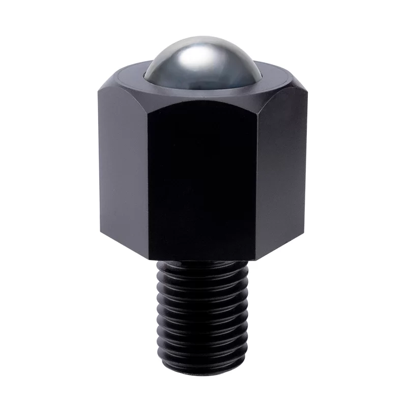
Série MSP – Bille à tige filetée
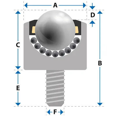
| Réf | Charge (lb)Charge (kg) | Poids | Bille Ø ″Bille Ø (mm) | A | B | C | D | E | F | À partir de € |  | |
|---|---|---|---|---|---|---|---|---|---|---|---|---|
| MSP8 | 29 13 | 0.046 0.021 | 5/16" 8 | 0.709 18 | 1.063 27 | 0.472 12 | 0.079 2 | 0.591 15 | M6 x 1.0 M6 x 1.0 | 5,17€ | PDF STEP | |
| MSP10 | 55 25 | 0.079 0.036 | 1/2" 12 | 0.787 20 | 1.173 29.8 | 0.701 17.8 | 0.118 3 | 0.472 12 | M8 x 1.25 M8 x 1.25 | 5,80€ | PDF STEP | |
| MSP11 | 55 25 | 0.097 0.044 | 1/2" 12 | 0.787 20 | 1.890 48 | 0.787 20 | 0.118 3 | 1.102 28 | M6 x 1.0 M6 x 1.0 | 7,49€ | PDF STEP | |
| MSP12 | 55 25 | 0.086 0.039 | 1/2" 12 | 0.866 ❋22 ❋ | 1.673 42.5 | 0.886 22.5 | 0.118 3 | 0.787 20 | M8 x 1.25 M8 x 1.25 | 7,04€ | PDF STEP | |
| MSP14 | 132 60 | 0.121 0.055 | 5/8" 15 | 0.945 24 | 1.260 32 | 0.788 20 | 0.197 5 | 0.472 12 | M6 x 1.0 M6 x 1.0 | 8,99€ | PDF STEP | |
| MSP15 | 132 60 | 0.183 0.083 | 5/8" 15 | 0.984 25 | 1.811 46 | 1.024 26 | 0.197 5 | 0.787 20 | M8 x 1.25 M8 x 1.25 | 9,29€ | PDF STEP | |
| MSP19 | 165 75 | 0.240 0.109 | 3/4" 19 | 1.181 30 | 1.831 46.5 | 1.024 26 | 0.189 4.8 | 0.807 20.5 | M8 x 1.25 M8 x 1.25 | 12,74€ | PDF STEP | |
| MSP22 | 397 180 | 0.564 0.256 | 7/8" 22 | 1.417 36 | 2.476 62.9 | 1.476 37.5 | 0.177 4.5 | 1 25.4 | M12 x 1.75 M12 x 1.75 | 23,02€ | PDF STEP | |
| MSP30 | 772 350 | 0.970 0.440 | 1 3/16" 30 | 1.772 45 | 2.724 69.2 | 1.724 43.8 | 0.256 6.5 | 1 25.4 | M12 x 1.75 M12 x 1.75 | 28,46€ | PDF STEP | |
| MSP45 | 1323 600 | 2.998 1.360 | 1 3/4" 45 | 2.441 62 | 4.224 107.3 | 2.598 66 | 0.335 8.5 | 1.626 41.3 | M20 x 2.5 M20 x 2.5 | 90,26€ | PDF STEP | |
| MSP8A | 18 8 | 0.046 0.021 | 5/16" 8 | 0.709 18 | 1.063 27 | 0.472 12 | 0.079 2 | 0.591 15 | M6 x 1.0 M6 x 1.0 | 5,70€ | PDF STEP | |
| MSP10A | 44 20 | 0.079 0.036 | 1/2" 12 | 0.787 20 | 1.173 29.8 | 0.701 17.8 | 0.118 3 | 0.472 12 | M8 x 1.25 M8 x 1.25 | 7,05€ | PDF STEP | |
| MSP11A | 44 20 | 0.095 0.043 | 1/2" 12 | 0.787 20 | 1.890 48 | 0.787 20 | 0.118 3 | 1.102 28 | M6 x 1.0 M6 x 1.0 | 8,36€ | PDF STEP | |
| MSP12A | 44 20 | 0.086 0.039 | 1/2" 12 | 0.866 ❋22 ❋ | 1.673 42.5 | 0.886 22.5 | 0.118 3 | 0.787 20 | M8 x 1.25 M8 x 1.25 | 10,42€ | PDF STEP | |
| MSP14A | 110 50 | 0.143 0.065 | 5/8" 15 | 0.945 24 | 1.260 32 | 0.788 20 | 0.197 5 | 0.472 12 | M6 x 1.0 M6 x 1.0 | 10,86€ | PDF STEP | |
| MSP15A | 110 50 | 0.183 0.083 | 5/8" 15 | 0.984 25 | 1.811 46 | 1.024 26 | 0.197 5 | 0.787 20 | M8 x 1.25 M8 x 1.25 | 11,14€ | PDF STEP | |
| MSP19A | 121 55 | 0.249 0.113 | 3/4" 19 | 1.181 30 | 1.831 46.5 | 1.024 26 | 0.189 4.8 | 0.807 20.5 | M8 x 1.25 M8 x 1.25 | 13,67€ | PDF STEP | |
| MSP22A | 397 180 | 0.564 0.256 | 7/8" 22 | 1.417 36 | 2.476 62.9 | 1.476 37.5 | 0.177 4.5 | 1 25.4 | M12 x 1.75 M12 x 1.75 | 27,73€ | PDF STEP | |
| MSP30A | 772 350 | 0.948 0.430 | 1 3/16" 30 | 1.772 45 | 2.724 69.2 | 1.724 43.8 | 0.256 6.5 | 1 25.4 | M12 x 1.75 M12 x 1.75 | 30,39€ | PDF STEP | |
| MSP45A | 1323 600 | 2.976 1.350 | 1 3/4" 45 | 2.441 62 | 4.224 107.3 | 2.598 66 | 0.335 8.5 | 1.626 41.3 | M20 x 2.5 M20 x 2.5 | 121,84€ | PDF STEP | |
| MSP8D | 7 3 | 0.042 0.019 | 5/16" 8 | 0.709 18 | 1.063 27 | 0.472 12 | 0.079 2 | 0.591 15 | M6 x 1.0 M6 x 1.0 | 6,21€ | PDF STEP | |
| MSP10D | 11 5 | 0.068 0.031 | 1/2" 12 | 0.787 20 | 1.173 29.8 | 0.701 17.8 | 0.118 3 | 0.472 12 | M8 x 1.25 M8 x 1.25 | 8,93€ | PDF STEP | |
| MSP11D | 11 5 | 0.088 0.040 | 1/2" 12 | 0.787 20 | 1.890 48 | 0.787 20 | 0.118 3 | 1.102 28 | M6 x 1.0 M6 x 1.0 | 8,28€ | PDF STEP | |
| MSP12D | 11 5 | 0.086 0.039 | 1/2" 12 | 0.866 ❋22 ❋ | 1.673 42.5 | 0.886 22.5 | 0.118 3 | 0.787 20 | M8 x 1.25 M8 x 1.25 | 11,01€ | PDF STEP | |
| MSP14D | 22 10 | 0.093 0.042 | 5/8" 15 | 0.945 24 | 1.260 32 | 0.788 20 | 0.197 5 | 0.472 12 | M6 x 1.0 M6 x 1.0 | 10,69€ | PDF STEP | |
| MSP15D | 22 10 | 0.152 0.069 | 5/8" 15 | 0.984 25 | 1.811 46 | 1.024 26 | 0.197 5 | 0.787 20 | M8 x 1.25 M8 x 1.25 | 11,09€ | PDF STEP | |
| MSP19D | 44 20 | 0.194 0.088 | 3/4" 19 | 1.181 30 | 1.831 46.5 | 1.024 26 | 0.189 4.8 | 0.807 20.5 | M8 x 1.25 M8 x 1.25 | 13,67€ | PDF STEP | |
| MSP22D | 44 20 | 0.441 0.200 | 7/8" 22 | 1.417 36 | 2.476 62.9 | 1.476 37.5 | 0.177 4.5 | 1 25.4 | M12 x 1.75 M12 x 1.75 | 27,37€ | PDF STEP | |
| MSP30D | 55 25 | 0.763 0.346 | 1 3/16" 30 | 1.772 45 | 2.724 69.2 | 1.724 43.8 | 0.256 6.5 | 1 25.4 | M12 x 1.75 M12 x 1.75 | 35,09€ | PDF STEP | |
| MSP45D | 55 25 | 2.425 1.100 | 1 3/4" 45 | 2.441 62 | 4.224 107.3 | 2.598 66 | 0.335 8.5 | 1.626 41.3 | M20 x 2.5 M20 x 2.5 | 117,84€ | PDF STEP | |
| MSP19SS | 165 75 | 24 109 | 3/4" 19 | 1.181 30 | 1.831 46.5 | 1.024 26 | 0.189 4.8 | 0.807 20.5 | M8 x 1.25 M8 x 1.25 | 26,76€ | PDF STEP | |
| MSP30SS | Demande de renseignements Demande de renseignements | Demande de renseignements Demande de renseignements | 1 3/16" 30 | 1.772 45 | 2.724 69.2 | 1.724 43.8 | 0.256 6.5 | 1 25.4 | M12 x 1.75 M12 x 1.75 | - | ||
| MSP45SS | Demande de renseignements Demande de renseignements | Demande de renseignements Demande de renseignements | 1 3/4" 45 | 2.441 62 | 4.224 107.3 | 2.598 66 | 0.335 8.5 | 1.626 41.3 | M20 x 2.5 M20 x 2.5 | - |
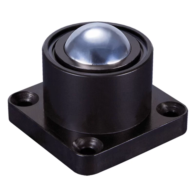
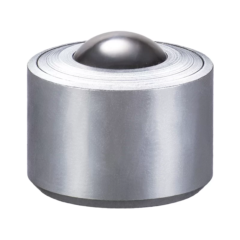
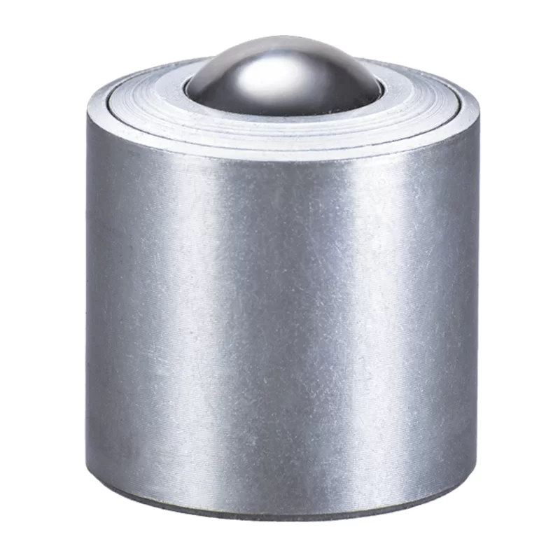
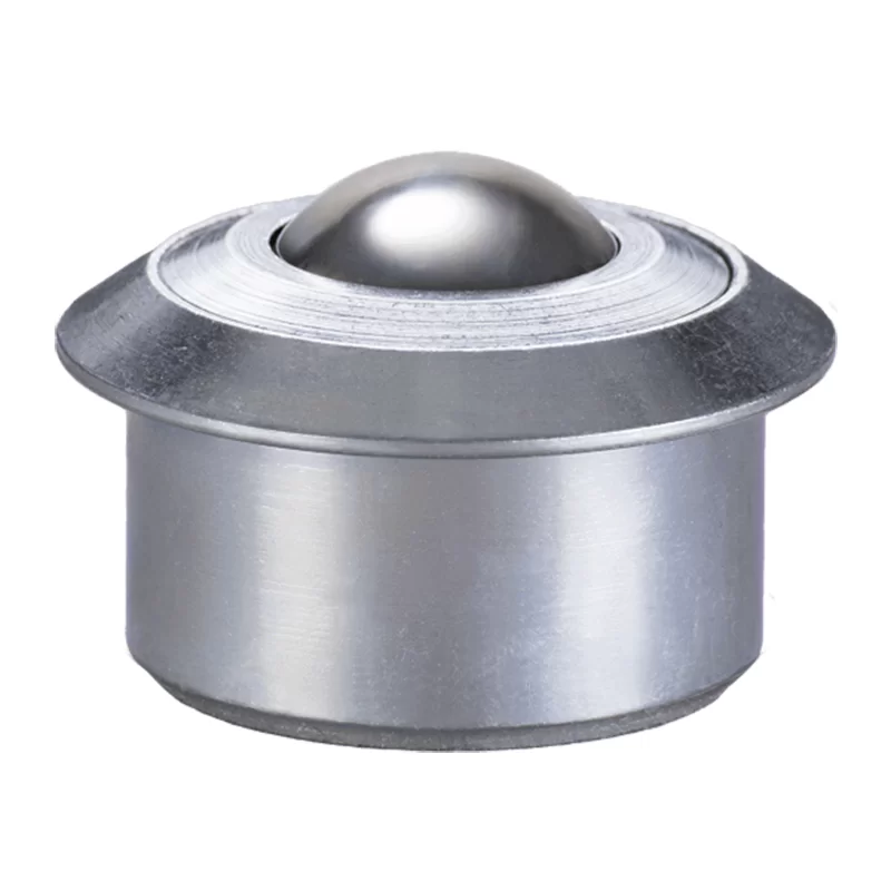
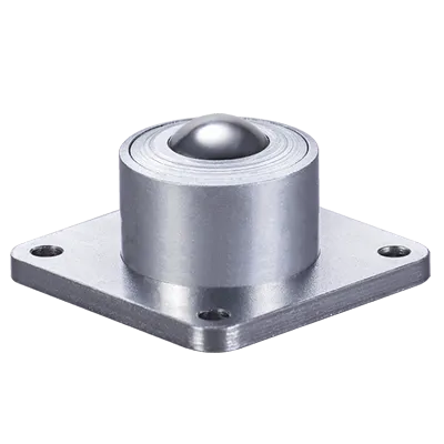
Les billes de manutention de la série MSP avec le raccord à boulon sont usinées en acier massif et cémentées pour résister à l’usure. Un capuchon supérieur en acier usiné renforcé protège contre les chocs dus à un mauvais alignement de l’objet transporté. Lubrifiés à vie et zingués pour résister à la corrosion. Standard materials; Body & cap AISI 1015, Balls AISI 52100. Stainless steel upgrade ‘A’ & ‘SS’ feature AISI420 balls Shock Resistance & body. The main ball sizes ≥19mm incorporates a felt seal to restrict contamination.
Cette série comporte un seul trou de drainage.
Filetage extérieur métrique (mâle).
1 : 0,002
1.5m/sec
-30/+100ºC
Orientation Horizontale / Haut
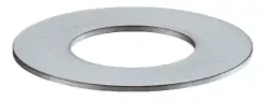
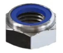
Kit d’écrous & rondelles Nyloc + Kit décrous à griffe pour bois
A utiliser avec les séries forte charge 81 & 91, la série gamme moyenne MSP et les roulettes Omnicaster.

| Charge moyenne | Réf | A | B | C | D | E | À partir de € | | ||
|---|---|---|---|---|---|---|---|---|---|---|
| MSP10 | MSP12 | MSP15 | MSP19 |  | T8 | 0.875 22.2 | 0.358 9.1 | 0.433 11 | M8 x 1.25 M8 x 1.25 | 0.051 1.3 | 0,47€ | ||
| MSP10 | MSP12 | MSP15 | MSP19 |  | W8 | 0.630 16 | 0.315 8 | 0.063 1.6 | M8 x 1.25 M8 x 1.25 | - | 0,09€ | ||
| MSP10 | MSP12 | MSP15 | MSP19 |  | N8 | 0.567 14.4 | 0.512 13 | 0.315 8 | M8 x 1.25 M8 x 1.25 | - | 0,16€ | ||
| MSP22 | MSP30 | | T12 | 1.063 27 | 0.551 14 | 0.551 14 | M12 x 1.75 M12 x 1.75 | 0.071 1.8 | 0,83€ | ||
| MSP22 | MSP30 | | W12 | 0.945 24 | 0.472 12 | 0.098 2.5 | M12 x 1.75 M12 x 1.75 | - | 0,16€ | ||
| MSP22 | MSP30 | | N12 | 0.831 21.1 | 0.748 19 | 0.472 12 | M12 x 1.75 M12 x 1.75 | - | 0,27€ |

Vous ne trouvez pas ce que vous cherchez?
Essayez de rechercher des mots-clés, numéros réfrérence, capacitè de charge et types de fixation.